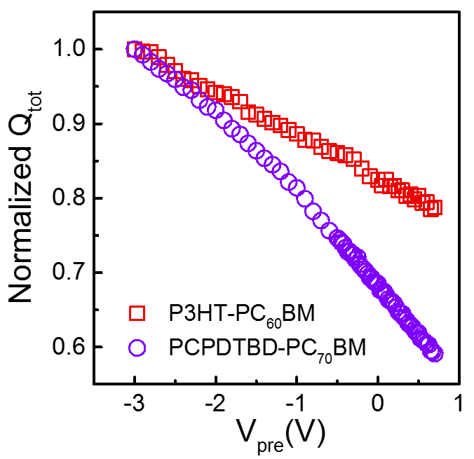
In a TDCF experiment the sample is illuminated by a laser pulse, while being kept at constant pre-bias voltage (Vpre, as shown in the scheme). After a delay td, a rectangular bias voltage (Vcoll) is applied to extract (collect) all remaining free carriers. The measured photocurrent response shows two current peaks, one directly after laser excitation, and the second after application of Vcoll. Integration of the area below the two curves yields the quantity of charges generated by laser excitation (Qpre) and extracted before (with Vpre applied) and during (Qcol) the application of the collection field, respectively. The sum of Qpre and Qcol equals the total number of generated charges Qtot.
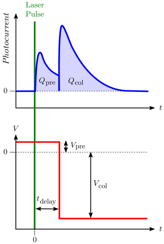
Figure 1: Photocurrent vs. time (left) and applied bias vs. time (right) schemes of typical TDCF experiment. For more explanations see text.
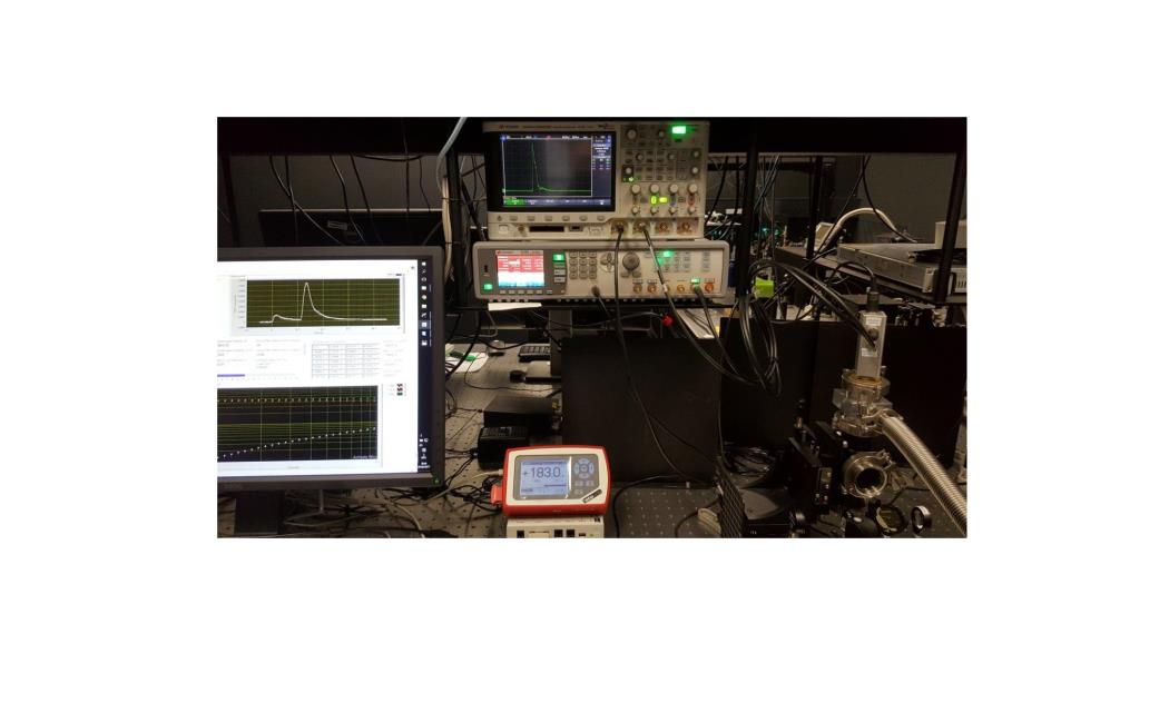
Our home-built TDCF setup was developed in collaboration with the research group of Professor Dieter Neher (University of Potsdam, Germany). The setup can be used with either our 3kHz fs-amplifier (Coherent LEGEND DUO) combined with two wavelength tunable TOPAS (Light Conversion) or Innolas AOT-MOPA (up to 50 kHz, 355 / 532 nm) as excitation source. A small device area is used to achieve a time resolution better than 5 ns. Samples can be measured under vacuum to avoid degradation in air.
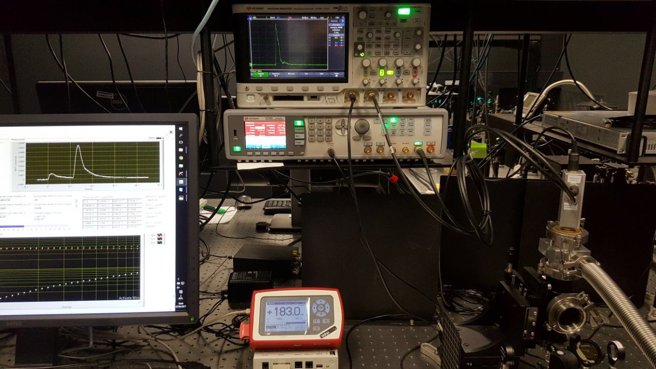
Figure 2: Home-built TDCF measurement rig showing test measurement: Sample chamber with attached TDCF measurement electronics (bottom right), oscilloscope and function generator (top middle), and computer screen with home-built LabView measurement software (left).
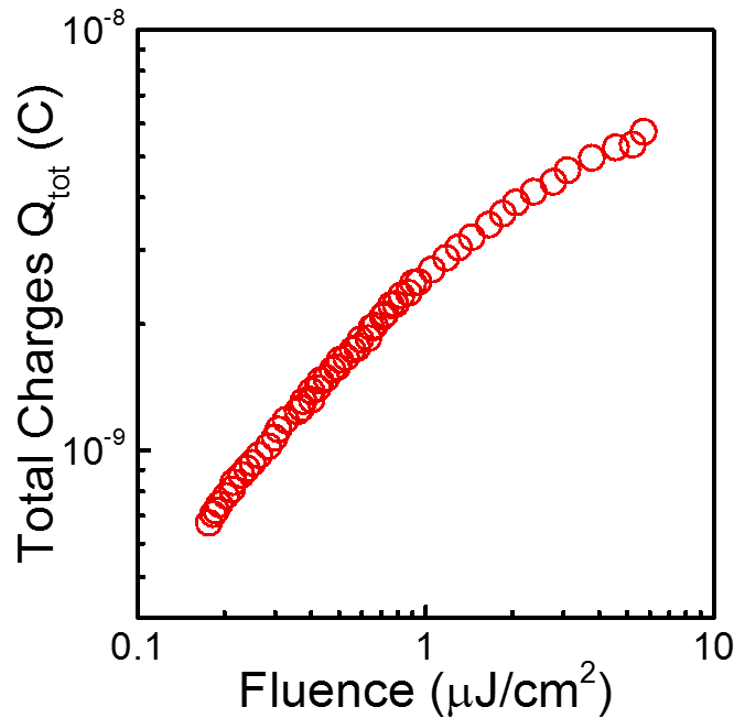
Figure 3: Total number of charges collected as a function of excitation fluence. Data were collected on a device with an active layer of PCPDTBT:PC71BM (Vpre = 0 V, and td = 10 ns). In the lower fluence range, the total number of generated charges increases linearly with pump fluence, implying negligible non-geminate recombination at low charge carrier concentrations.
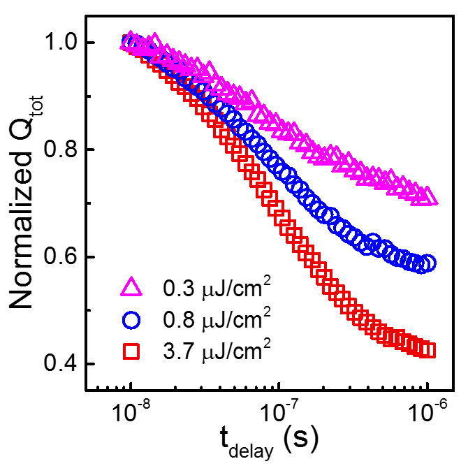
Figure 4: Normalized number of charges as a function of delay time. Data were collected on a device with an active layer of PCPDTBT:PC71BM using different excitation fluences (with Vpre = 0 V). The lowest fluence chosen shows negligible non-geminate recombination.